A network design assignment, graded as you draw
· 2 min read
Guided mode turns the usual course deliverables into eight steps on one diagram, checked live, with a VLSM planner and a Containerlab export at the end.
Networking courses ask for the same deliverables every term: requirements, a segmentation plan, an IP addressing table, logical and physical topology, cabling, security zones and a short write-up. Students usually produce them in four tools and hand in a folder that does not agree with itself.
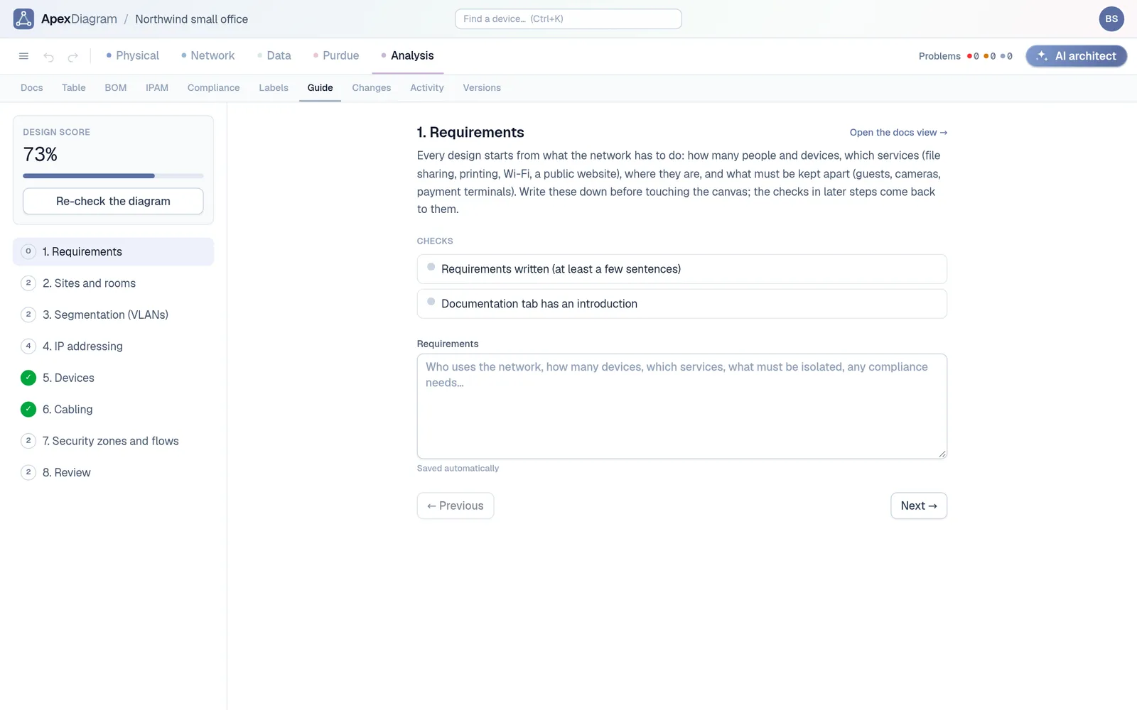
ApexDiagram's Guide tab turns that assignment into eight steps on one diagram, and checks each step against the diagram as you work.
The eight steps
- Requirements. A written answer: who uses the network and what it must do.
- Sites and rooms. A site and a room or rack, with every device placed.
- Segmentation. At least two VLANs, including a management VLAN, and a written rationale.
- IP addressing. Valid subnets, an address inside its subnet for every networked device, no duplicates, and the plan written down.
- Devices. An edge firewall or router, a switch and end devices, with make and model recorded.
- Cabling. Nothing orphaned, cable types recorded, rack units set.
- Security zones and flows. Data flows with protocols, Purdue levels for any OT devices, and a written policy.
- Review. No errors from the diagram assistant, at most three warnings, and a page of documentation.
Each step has a short lesson and a link to the view where the work happens. The score is the share of checks passed, and Re-check recomputes it from the live diagram.
The Guide tab: eight steps, live checks and a design score
Why it teaches better than a blank canvas
The checks are the same ones a professional sees. Put a host outside its subnet and step 4 fails, with the diagram assistant pointing at the device. Leave a switch unconnected and step 6 fails. Students learn why the rule exists by breaking it.
Plan addresses properly
The IPAM tab includes a VLSM planner. Give it a base block and a list of named host counts, and it returns aligned subnets, largest first, plus the leftover space. One click creates the VLANs and subnets on the diagram.
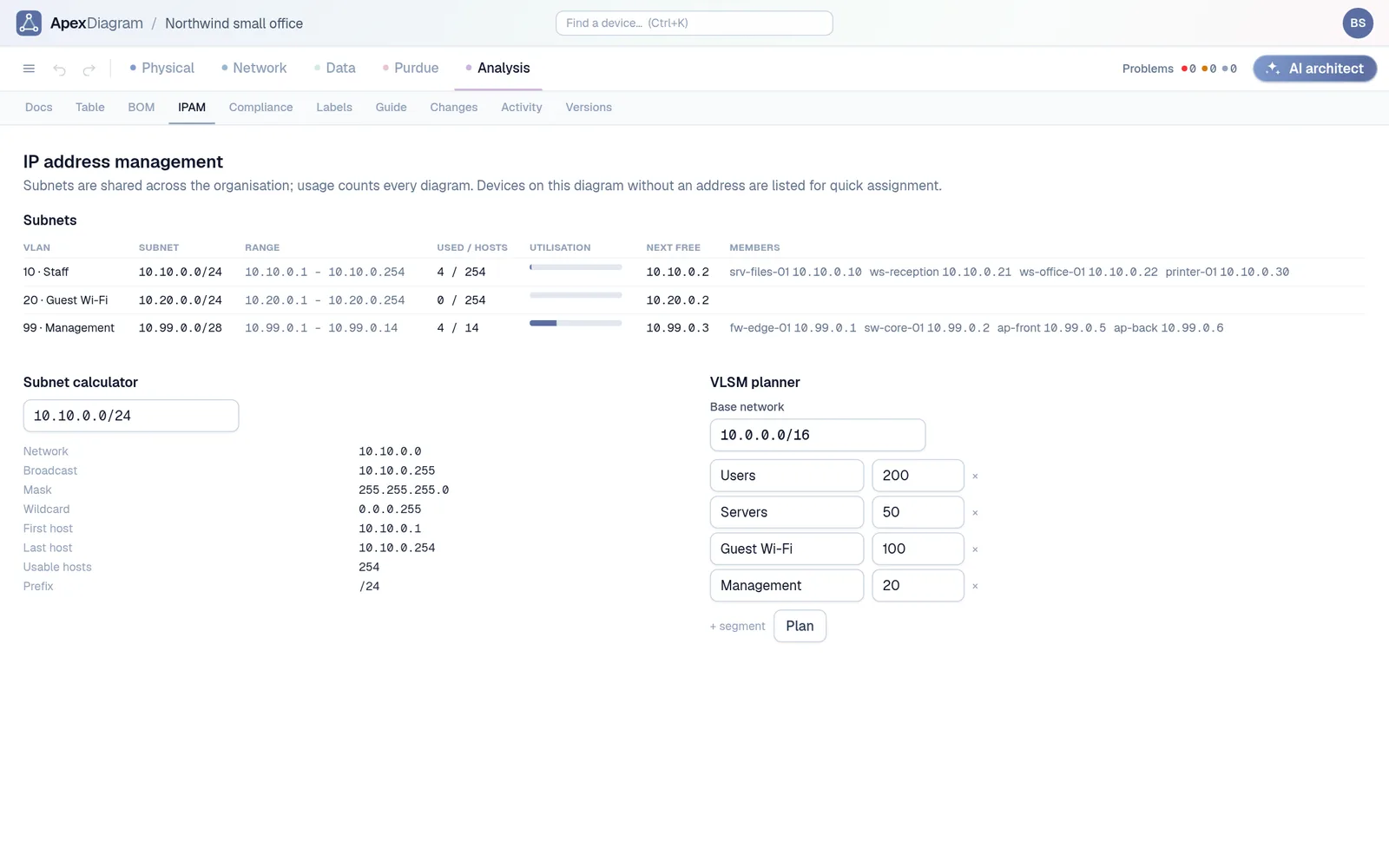 The IPAM tab, where the VLSM planner lives
Boot what you designed
When the design is done, Export, Containerlab topology turns the Network view into a lab file. Routers and switches become Nokia SR Linux nodes, firewalls become VyOS, and hosts become small Linux containers with their management IPs. Run containerlab deploy and test the network you drew.
For students and educators
Guided mode, every view and the Containerlab export are there from the first diagram. See plans and pricing.
Document your network once, keep it current
One network graph, four synchronized views, a linter and a bill of materials. Import the Visio or draw.io file you already have.
Join the beta